The semester has finally ended, and I didn’t fail any of my classes. I consider that a success!
Immediately after finals, I once again picked up “Understanding Digital Signal Processing” by Richard Lyons; I plan on slowly working through all of the chapters in the book. I’ve just finished the discrete Fourier Transform section and learned a lot about leakage, the Nyquist criterion, windowing and a whole bunch of other weird digitization effects. I’m currently on FIR filters.
I managed to get the FPGA camera module in a semi functional state. The main problem was that the I2C commands were not being properly registered by the camera when the FPGA issued them. In the process of debugging this, I wrote a little arduino script for the KB2040 which allowed me to read and write arbitrary registers in the camera (see below).
#include <Wire.h>

#define I2C_ADDR 0x3C

#define READ_PIN D4
#define WRITE_PIN D5

uint16_t addresses[] = {0x3008,0x3008,0x3103,0x3017,0x3018,0x302c,0x4740,0x4713,0x5001,0x3000,0x3002,0x3004,0x3006,0x5000,0x5001,0x5003,0x3a02,0x3a03,0x3a08,0x3a09,0x3a0a,0x3a0b,0x3a0d,0x3a0e,0x3a0f,0x3a10,0x3a11,0x3a13,0x3a14,0x3a15,0x3a18,0x3a19,0x3a1b,0x3a1e,0x3a1f,0x3600,0x3601,0x3c01,0x3c04,0x3c05,0x3c06,0x3c07,0x3c08,0x3c09,0x3c0a,0x3c0b,0x460c,0x4001,0x4004,0x5180,0x5181,0x5182,0x5183,0x5184,0x5185,0x5186,0x5187,0x5188,0x5189,0x518a,0x518b,0x518c,0x518d,0x518e,0x518f,0x5190,0x5191,0x5192,0x5193,0x5194,0x5195,0x5196,0x5197,0x5198,0x5199,0x519a,0x519b,0x519c,0x519d,0x519e,0x5381,0x5382,0x5383,0x5384,0x5385,0x5386,0x5387,0x5388,0x5389,0x538a,0x538b,0x5300,0x5301,0x5302,0x5303,0x5304,0x5305,0x5306,0x5307,0x5308,0x5309,0x530a,0x530b,0x530c,0x5480,0x5481,0x5482,0x5483,0x5484,0x5485,0x5486,0x5487,0x5488,0x5489,0x548a,0x548b,0x548c,0x548d,0x548e,0x548f,0x5490,0x5580,0x5583,0x5584,0x5586,0x5587,0x5588,0x5589,0x558a,0x558b,0x501d,0x3008,0x3c00,0x3800,0x3801,0x3802,0x3803,0x3804,0x3805,0x3806,0x3807,0x3808,0x3809,0x380a,0x380b,0x380c,0x380d,0x380e,0x380f,0x3810,0x3811,0x3812,0x3813,0x5001,0x3820,0x3821,0x4514,0x4520,0x3814,0x3815,0x3039,0x3034,0x3035,0x3036,0x3037,0x3108,0x3824,0x460c,0x3103,0x501f,0x4300,0x3002,0x3006,0x3800,0x3801,0x3802,0x3803,0x3804,0x3805,0x3806,0x3807,0x3808,0x3809,0x380a,0x380b,0x380c,0x380d,0x380e,0x380f,0x3810,0x3811,0x3812,0x3813,0x5001,0x3820,0x3821,0x4514,0x4520,0x3814,0x3815,0x3039,0x3034,0x3035,0x3036,0x3037,0x3108,0x3824,0x460c,0x3103,0x501f,0x4300,0x3002,0x3006,0x3820,0x3821,0x4514,0x4520,0x3814,0x3815,0x3820,0x3821,0x4514,0x4520,0x3814,0x3815};
uint8_t data[] = {0x82,0x42,0x13,0xff,0xff,0xc3,0x21,0x02,0x83,0x00,0x1c,0xff,0xc3,0xa7,0xa3,0x08,0x03,0xd8,0x01,0x27,0x00,0xf6,0x04,0x03,0x30,0x28,0x60,0x43,0x03,0xd8,0x00,0xf8,0x30,0x26,0x14,0x08,0x33,0xa4,0x28,0x98,0x00,0x08,0x00,0x1c,0x9c,0x40,0x22,0x02,0x02,0xff,0xf2,0x00,0x14,0x25,0x24,0x09,0x09,0x09,0x75,0x54,0xe0,0xb2,0x42,0x3d,0x56,0x46,0xf8,0x04,0x70,0xf0,0xf0,0x03,0x01,0x04,0x12,0x04,0x00,0x06,0x82,0x38,0x1e,0x5b,0x08,0x0a,0x7e,0x88,0x7c,0x6c,0x10,0x01,0x98,0x10,0x10,0x18,0x19,0x10,0x10,0x08,0x16,0x40,0x10,0x10,0x04,0x06,0x01,0x00,0x1e,0x3b,0x58,0x66,0x71,0x7d,0x83,0x8f,0x98,0xa6,0xb8,0xca,0xd7,0xe3,0x1d,0x06,0x40,0x10,0x20,0x00,0x00,0x10,0x00,0xf8,0x40,0x02,0x04,0x00,0x00,0x00,0xf0,0x0a,0x3f,0x06,0xaf,0x05,0x00,0x02,0xd0,0x0a,0x54,0x02,0xe8,0x00,0x10,0x00,0x08,0x83,0x01,0x01,0xaa,0x0b,0x31,0x31,0x00,0x1a,0x11,0x28,0x02,0x16,0x02,0x22,0x13,0x01,0x61,0x1c,0xc3,0x00,0x00,0x00,0xf0,0x0a,0x3f,0x06,0xaf,0x05,0x00,0x02,0xd0,0x0a,0x54,0x02,0xe8,0x00,0x10,0x00,0x08,0x83,0x01,0x01,0xaa,0x0b,0x31,0x31,0x00,0x1a,0x11,0x28,0x02,0x16,0x02,0x22,0x13,0x01,0x61,0x1c,0xc3,0x01,0x01,0xaa,0x0b,0x31,0x31,0x01,0x01,0xaa,0x0b,0x31,0x31};
int array_length = 0;

volatile char read_running = 0;
volatile char prev_read_running = 0;

volatile char write_running = 0;
volatile char prev_write_running = 0;

volatile char scan_running = 0;
volatile char prev_scan_running = 0;

int SCCB_Write(uint8_t IP_Addr, uint16_t subaddr, uint8_t write_data) {
  uint8_t lower = (subaddr & 0xFF);
  uint8_t upper = ((subaddr >> 8) & 0xFF);
  Wire.beginTransmission(I2C_ADDR);
  Wire.write(upper);
  Wire.write(lower);
  Wire.write(write_data);
  int error = Wire.endTransmission();
  if (!error) {
    return 0;
  }
  return 1;
}

uint8_t SCCB_Read(uint8_t IP_Addr, uint16_t subaddr) {
  uint8_t output = 0;
  uint8_t lower = (subaddr & 0xFF);
  uint8_t upper = ((subaddr >> 8) & 0xFF);
  Wire.beginTransmission(I2C_ADDR);
  Wire.write(upper);
  Wire.write(lower);
  Wire.endTransmission();
  Wire.requestFrom(I2C_ADDR, 1);
  output = Wire.read();
  return output;
}

void setup() {
  pinMode(READ_PIN, INPUT);
  pinMode(WRITE_PIN, INPUT);
  //  pinMode(SCAN_ADDR, INPUT);
  Wire.setSDA(D2);
  Wire.setSCL(D3);
  array_length = sizeof(addresses) / sizeof(addresses[0]);
  Serial.begin(19200);
  Wire.begin();
}

void loop() {
  read_running = digitalRead(READ_PIN);
  if ((read_running != prev_read_running) && (prev_read_running == 0)) {
    Serial.println("Starting Transaction (Read): ");
    for (int i = 0; i < array_length; ++i) {
      uint8_t data = SCCB_Read(I2C_ADDR, addresses[i]);
      Serial.printf("%0x %0x\n", addresses[i], data);
    }
    Serial.println("Finished Transaction (Read): ");
  }
  prev_read_running = read_running;

  write_running = digitalRead(WRITE_PIN);
  if ((write_running != prev_write_running) && (prev_write_running == 0)) {
    Serial.println("Starting Transaction (Write): ");
    for (int i = 0; i < array_length; ++i) {
      SCCB_Write(I2C_ADDR, addresses[i], data[i]);
      Serial.printf("%0x %0x\n", addresses[i], data[i]);
      uint8_t data = SCCB_Read(I2C_ADDR, addresses[i]);
      Serial.printf("Read Back: %0x %0x\n", addresses[i], data);
    }
    Serial.println("Finished Transaction (Write): ");
  }
  prev_write_running = write_running;
}
The I2C lab code I was given didn’t provide the read functionality, and I didn’t want to string together a bunch of modules in the FPGA to write the register values over USB. The meaning behind the various addresses and data values can be found here. For some reason, the camera responded to the KB2040 I2C commands, but not the FPG ones? In any case, after doing all of that, I got the camera to generate the clock and sync signals, which allowed something to be displayed.
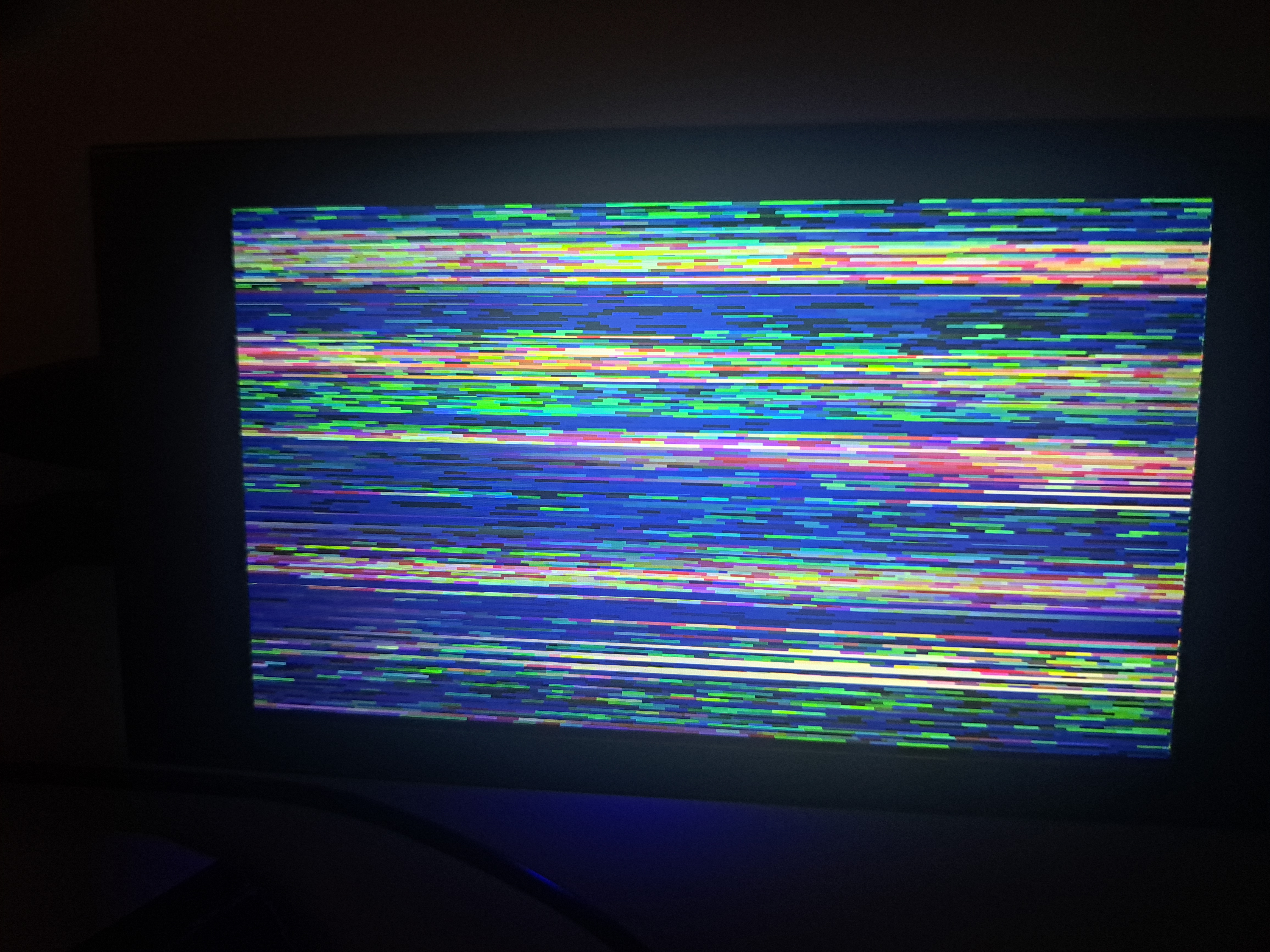
Unfortunately, it’s still a jumbled mess of color; I’m trying to figure out why it doesn’t display the right image. I’m pretty certain that it’s reading the live feed, since if I cover the camera, all of the pixels get darker. I need to dig through my testbench more thoroughly (and perhaps give in and write some frame data over UART to analyze…)
As part of my PhD work, I’m trying to read a paper every day which is pertinent to my work. It’s going well so far, and I’ve covered a bunch of topics (normalizing flows, pulsar based timing standards, the ephemeris of Jupiter etc.). Hopefully this becomes a habit…