Notes taken while reading “The Art of Electronics”. I realized that my electronics knowledge is a bit spotty and more theoretically inclined, hence why I’m doing this.
- The Basics, Because You Have to Start Somewhere
- Transistors (BJTs)
The Basics, Because You Have to Start Somewhere
-
There are two quantities that we care about with circuits: Voltage and Current
- Voltage is the work required to move a unit charge through an electric field
- Current is the rate of flow of electrons pas a point
- Current flows through things, voltages are applied across things
- Voltages at a point are in reference to some “ground”, which is the arbitrary point where the potential is 0.
-
Good things to know
- Conservation of current applies at each node in a circuit (Kirchhoff’s current law)
- The voltage between two points is independent of the path taken (Kirchhoff’s Voltage law)
- The power consumed by a circuit equals $P = VI$
Resistors
- Lot’s of electronic devices work by having quirky relationships between current (I) and voltage (V). The humble resistor has a very simple relationship: it’s just linear
- The ideal resistor follows the relationship: $R = \frac{V}{I}$, where R is the resistance
- Real resistors don’t always behave like this, but for most things, this works good enough
- The ideal resistor follows the relationship: $R = \frac{V}{I}$, where R is the resistance
- Putting resistors in series yields $R = \Sigma_{i} R_{i}$
- You will always get a larger resistance this way
- Putting resistor in parallel yields $\frac{1}{R} = \Sigma =\frac{1}{R_{i}}$
- You always get a smaller resistor value this way
- When talking about devices that don’t obey this nice linear relationship, it’s sometimes beneficial to take about the $\frac{\delta V}{\delta I}$ at a particular voltage, particular for small voltage values
- This is called small-signal resistance (or incremental resistance. Or dynamic resistance.)
Resistor Rule’s of Thumb
- A large resistor in series (parallel) with a small resistor has the resistance of the larger (smaller) one
- As a consequence of this, you can tweak effective resistances
- To trim up to a value, get a resistor smaller than the target, then add a small values in series
- To trim up to a value, get a resistor that’s marginally larger than the target, then connect a (much larger) resistor in parallel
- Rough rule of thumb is use proportions: If you want to lower a value by 1%, put a resistor 100 times as large in parallel
- As a consequence of this, you can tweak effective resistances
- The resistance of n resistors of value R in parallel is equivalent to $\frac{R}{n}$
- When designing circuits, you shouldn’t hyperfocus on getting exact values unless absolutely necessary. The reason is two fold
- Resistors have tolerances on them which means they may not exactly align with the values you want
- A good design shouldn’t care about having the “perfectly tuned” component
Voltage Dividers
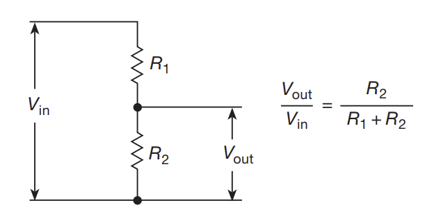
- The voltage across a resistor is given by $V_{i} = V_{in}\frac{R_{i}}{\Sigma_{j}{R_{j}}}$
- Useful to generate a new reference voltage from a higher voltage source
- That’s not particularly interesting (you learned this this high school physics). Something that is marginally interesting is that you can use a voltage divider to think about a circuit:
- The $V_{in}$ and top resistor can be one system, and the bottom resistor can be the next stage in the signal processing chain
Thevenin Equivalence
- The previous point works because of Thevenin’s theorem:
- Any two terminal network of resistors and voltage source is equivalent to a single resistor R in series with a single voltage source
- There is a dual version called Norton’s theorem which swaps voltage source in series for a current source in parallel
- To calculate Thevenin equivalent, you do the following:
- Remove the Load resistor (ie. the location where you care about the voltage and current)
- Remove all the power sources (short voltages, open currents)
- Use series and parallel reductions to reduce resistor network down to $R_{th}$
- Reinstate the voltage sources, then find the voltage across the two load terminals
Misc Use Cases
- Clamping input current to another part of the circuit
Capacitors
- Useless in DC applications. Extremely useful for AC stuff
- Can be used to make frequency dependent voltage dividers
- Governing equation: $Q = CV$
- Alternatively: $I = C\frac{dV}{dt}$
- Hence, a constant current in a capacitor will yield a rising voltage up to the max energy of $\frac{1}{2}CV^{2}$
- Typical construction is two metal plates with a dielectric between them. Formula for this is $C = \frac{\epsilon A}{d}$
- Alternatively: $I = C\frac{dV}{dt}$
- Ideal capacitors can’t dissipate current since the voltage and current are 90 degrees out of phase with each other
- Real capacitors have a little bit of resistance to them, so they do dissipate heat
- In series, Capacitors get added like resistors in parallel
- In parallel, capacitors get added like resistors in series
Common Applications
- Bypass: At high frequencies, capacitors act like a short, so they can be used to shunt high frequency signals to ground. Useful for eliminating noise from DC signal
- Coupling: Capacitors act as an open circuit for DC signals, so they can be used to block the average DC signal between different parts of a circuit
RC Time Constants
- From Kirchoff’s laws, we can see that placing a resistor and capacitor in either series or parallel (doesn’t matter?) causes the voltage across the capacitor to exponetially ramp up and down
- The rate of the expotential is governed by the RC constant (units of time)
- Note: It takes roughly $t = 5RC$ for the capacitor to “completely” charge and discharge to it’s highest and lowest point
- The rate of the expotential is governed by the RC constant (units of time)
- The applications of RC circuits include
- Delays: If you need to delay an input signal by some amount, the rising/falling voltage of the capacitor can be used to introduce the delay
- In a similar vein, You can use RC circuits to time things
Frequency Filters
Low pass filter
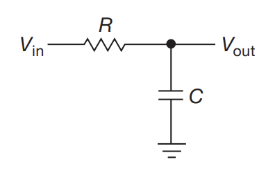
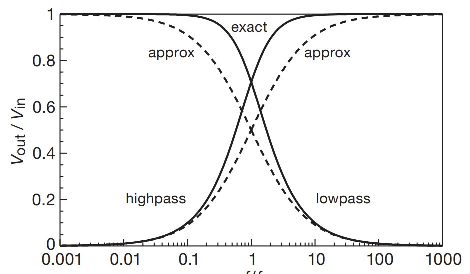
- Can filter out certain frequency components of input signal with low/high pass filters (swap resistor and capacitor for high pass)
- You should choose R values of a reasonable load
- This means the load shouldn’t be so small that it’s hard to drive
- … but not so large that the RC constant gets so high that you get pileup
- Audio stuff typically uses 10k$\Omega$
- To avoid distortion, for a square wave of pulse duration T, we want to choose $RC » T$
- This causes a droop of about $\frac{T}{\tau}$, with a coresponding overshoot at the next transition
Differentiators
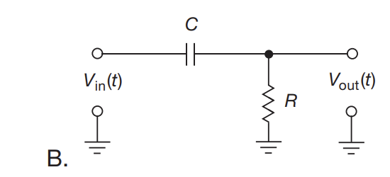
- In an ideal world, we would be able to just run an AC voltage source across a capacitor and extract the derivative that way. Unfortunately, we can’t measure this current
- To get around this, we place a current sensing resistor in series. This allows us to sense the changes, but now you no longer get a pure derivative of $V_{in}$. From Kirchoff’s law
- $I = C \frac{d}{dt}(V_{in}-V_{out}) = \frac{V_{out}}{R}$
- If the RC constant is chosen such that $\frac{dV_{out}}{dt} « \frac{dV_{in}}{dt}$, then we can roughly say $V_{out} \approx RC\frac{dV_{in}}{dt}$
- To get the this designed approximation, you need to keep R small, but not too small to avoid “loading” the input
- This type of circuit is useful for leading and trailing edge detection
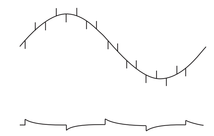
- Sometimes, you make an unintentional differentiator due to capacitive coupling. This can signals in other parts of the circuit to act as a differentiator on a signal in a different part
Integrators
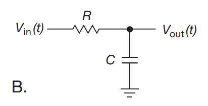
- Integrators follow a similar derivation as differentiators
- Instead of making RC small, you want to make RC as large as possible to better approximate the ramping voltage of an ideal capacitor
- With this assumption, the output voltage follows: $V = \frac{1}{RC} \int V_{in} dt + constant$
Inductors
- Governing equation: $V = L \frac{dI}{dt}$
- Energy stored ins $U = \frac{1}{2} LI^{2}$
- Putting a constant voltage across an inductor causes the current to rise linearly
- Wheeler’s formula for simple air-core coils: $L \approx K \frac{d^{2}n^{2}}{18d+40l} \mu H$
- K= 1.0 or 0.395 depending on units (inches/centimeters)
- Accurate to 1% if l > 0.4d
Applications
Voltage Converters
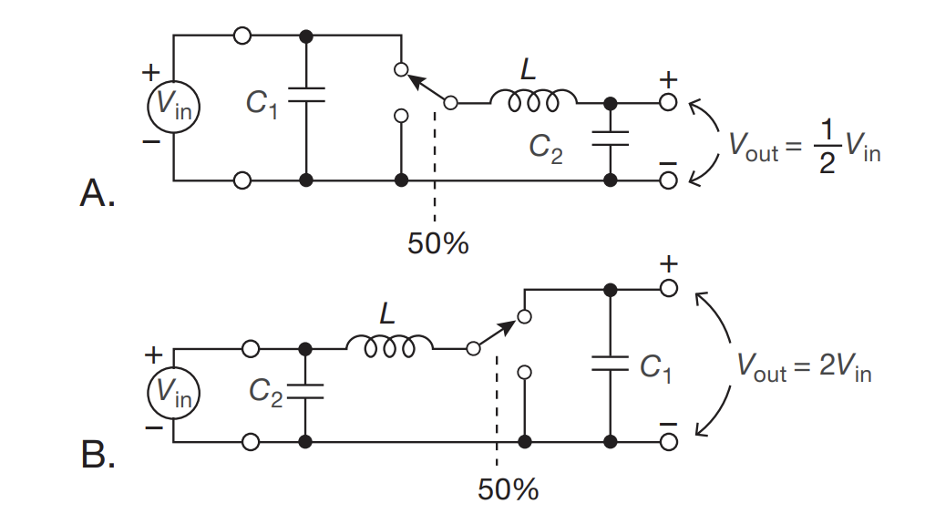
- Above shows a “synchronous boost/buck converter”
- The above shows how a inductor can enable transforming a DC voltage source to a different value, including raising the voltages
- The 50% thing means that the switch spends 50% of the time connected to each terminal at a very high switching rate
- The capacitor across output terminals are meant to hold the voltage in the interim period
- This is also very efficient compared to a voltage divider
Transformers
- Putting two inductors with a different number of windings allows power transfer between them. So you can step up/ step down the voltage at the cost of decreasing/increasing the current
- Allows noise isolation between circuits
- Real transformers have a ton of quirks to them
- There is an effective parallel inductance (magnetizing inductance), which prevents a DC transformer from existing
- There is also an effective series inductance (leakage inductance), which causes a load current dependent voltage drop
- There’s also winding resistance, core losses, capacitance, external coupling etc.
Diodes
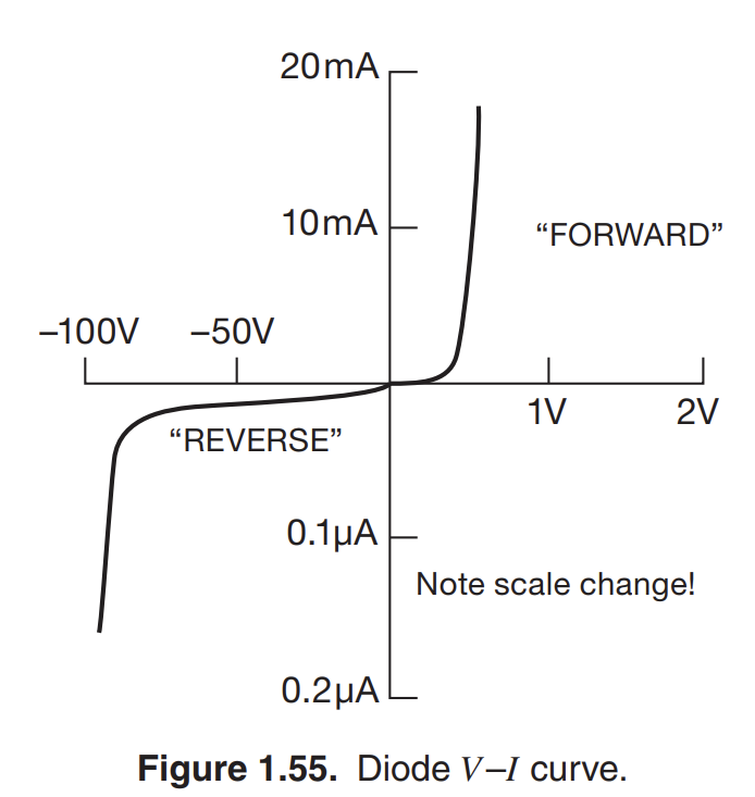
- There are passive devices that only allow current to flow in one direction. You can think of them as a one-way wire
- In reality, that’s not quite true, the IV curve shows that diode permit a very small amount of current to flow in the reverse, and that you need to hit some minimal voltage for the current to really start flowing (this voltage is the forward voltage drop)
- Diodes don’t have resistance per say (they do have dynamic resistance though…)
- Placing a diode in a circuit prevents a mapping to a Thevenin equivalent
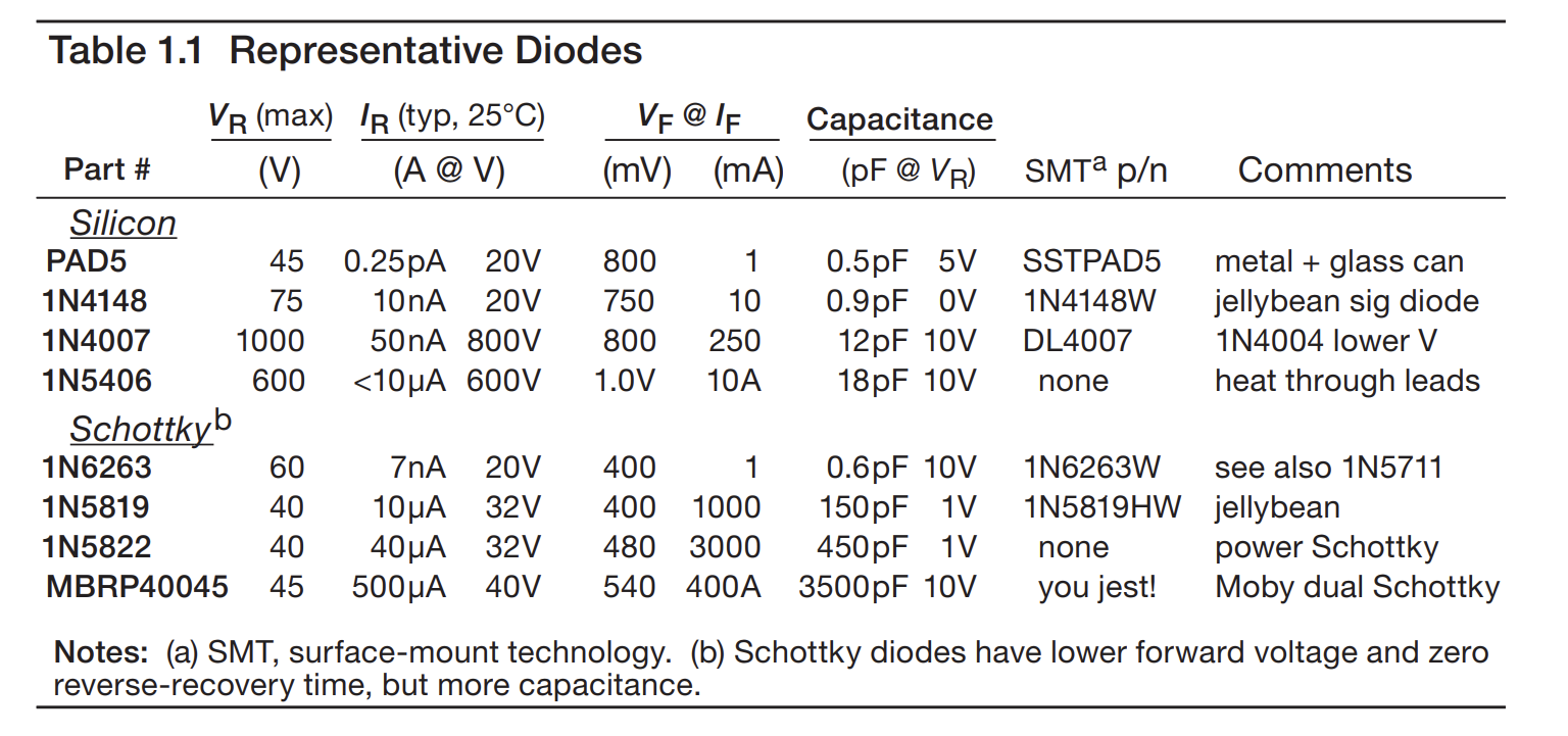
- Jellybean.
Applications
Rectifiers
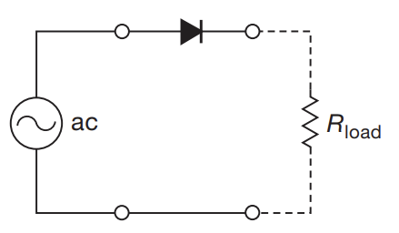
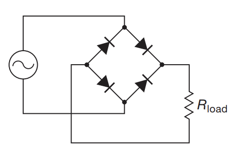
-
The above allows one to convert a AC signal to a signal that is strictly positive
-
To make a constant DC power supply of of these, one needs to place a fat capacitor across the output terminals. This cap will charge on the rising part, and discharge at the falling part, allowing a stable DC voltage (which some ripple current)
- From $\Delta V = \frac{I}{C} \Delta t$. $\Delta t$ is conservatively $\frac{1}{2f}$ for a full bridge rectifier, where f is the frequency of the input AC. Hence, the peak-to-peak ripple current is $\Delta V = \frac{I_{load}}{2fC}$
-
The signal doesn’t necessarily need to be sinusoidal. Any signal where you only want a positive voltage can be rectified
Dual Rail Power Supply
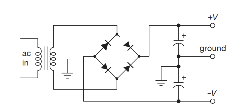
- Allows you to get negative voltages, which many ICs desperately want
Voltage Multipliers
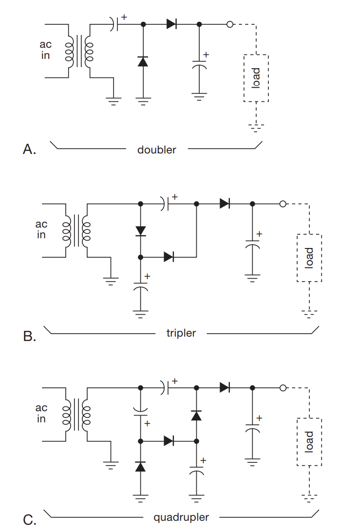
- For when you need large DC voltages that draw little current
- General case is called a Cockcroft–Walton generator
Biasing
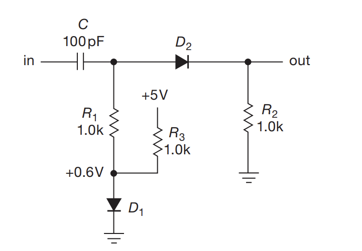
- In the above, we want D2 to always be conducting. Remember that to act as an ideal conductor, the diode needs to overcome some forward voltage drop. Suppose that it’s 0.6 V.
- If the input signal is smaller than 0.6 V, then no output will appear after D2
- Placing D1 in parallel with D2 generates a bias in the signal
- this means that there is a constant DC offset added to the incoming signal
- This allows smaller signals to get properly transmitted
- In comparison to voltage divider, this allows near-perfect compensation, inducing tempurature dependency
Logic Gates
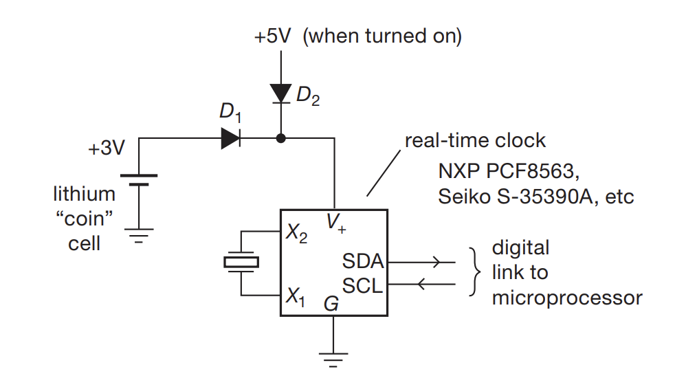
- Can be utilized to implement simple logic gates
- Above shows a some sort of power supply fail over
- Normal operation utilizes the higher voltage
- if you unplug, the RTC continues withough delay using 3.3V instead
Clamps
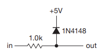
- Diodes can be used to prevent signals from exceeding a certain range value. If the input exceeds 5.6 V, the signal gets sinked into the +5V source
- Problem with this is the necessary addition of 1k$\Omega$ increases the Thevenin resistance
- Can use a voltage divider to provide the reference voltage (or Op-Amp based circuit)
Limiters
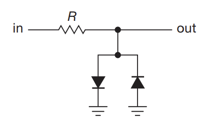
- The above limits the voltage of the output to $\pm 0.6 V$, since if this exceeds the voltage, the current gets drained through one of the diodes
Logarithm
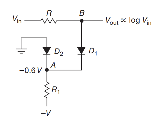
- Small signal of diode IV curve is roughly exponential. Can use above to produce log of input voltage
Inductive Kickback
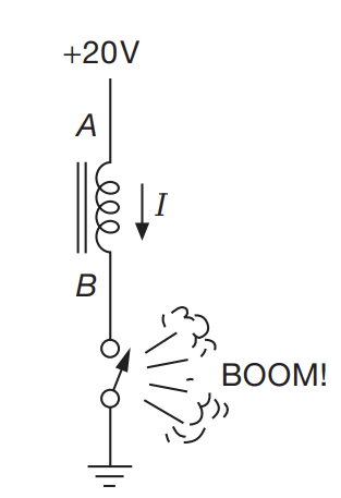
- Closing the switch draws huge current. Putting a diode in parallel allows the current a route to die out
Transistors (BJTs)
- Simplest active component (ie. needs external power to function)
- 3 terminal device
- Voltage of each terminal w.r.t. ground is referred to by $V_{C}, V_{B}, V_{E}$ respectively
- B is base, C is collector, E is emitter
- Voltage between terminals uses a double subscript: $V_{BE}$ is base-to collector
- $V_{CC}$ and $V_{EE}$ denotes positive and negative supply rails
BJTs (Bipolar Junction Transistors)
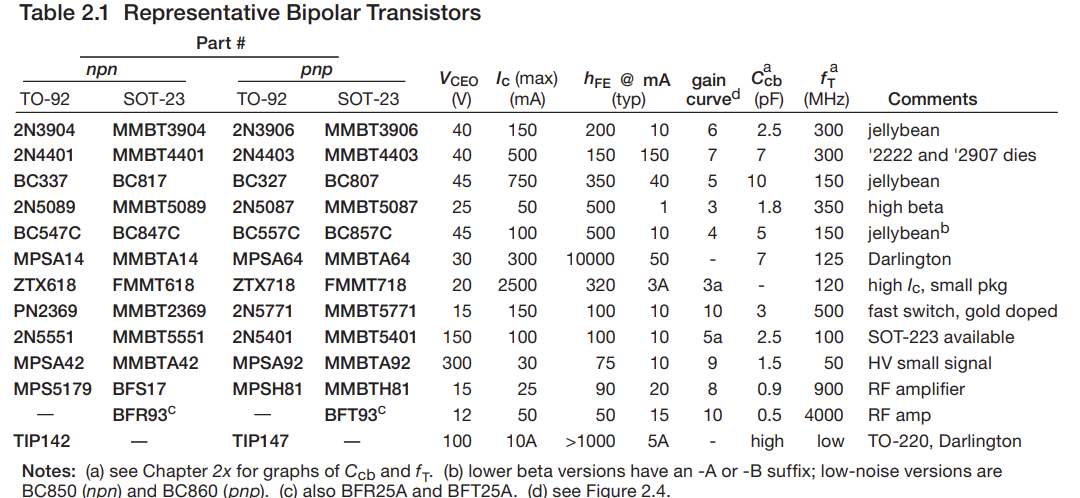
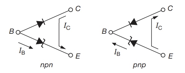
- Comes in two flavors: npn and pnp
- With respect to npn (pnp simply reverses all polarities)
- Polarity: The collector must be more positive than the emitter
- Juntions: The base-collector and base-emittor behave like diodes
- Typically, the base-emitter is conducting, and the base-collector is reverse-biased
- Typically, $V_{B} \approx V_{E}+ 0.6 V$ for normal operation
- There are certain max $I_{B}, I_{C}, V_{CE}$ that cannot be exceeded
- Assuming the above 3 hold, then the following relationship holds
- $I_{c} = h_{FE}I_{B} = \beta I_{B}$ where $\beta$ is the current gain (typically 100)
- Your design should be resistant to a particular $\beta$ value since they fluctuate with a whole bunch of effectively random factors
Transistor Switches and Saturation
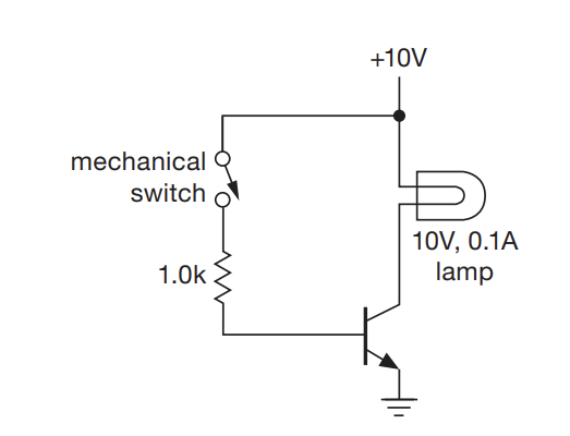
- The above is an example of using a transistor to drive a high amperage lamp with a low voltage signal
- The forward $V_{BE}$ drop is 0.6 V, which means that there is a current of 9.4 mA from the base to emitter
- Naively, you would expect that $I_{C} = 940 mA$ for $\beta = 100$. However, this only occurs if the collector has a higher voltage than the emitter.
- Saturation occurs when the collector drops to it’s lowest possible value (typically 0.05-0.2 V)
- The base resistor is choosen to overdive the base (provide 9.4 mA when 1.0mA would have barely cut it)
- This is necessary since beta drops at low $V_{CB}$ voltages
- For real circuits, some things to keep in mind
- If the load voltage can swing negative, place a diode in series with the collector to prevent collector-base conduction on negative swings
- For inductive loads, protect the transistor with a diode across the load
- Why use transistors as switches?
- Can be driven electrically
- Allow rapid switching
- Can switch multiple different circuits with one signal
- mechanical switches wear out
- mechanical switches can bounce and trigger a system multiple times
- You can use DC control values instead of directly running signals through cables
Switching From High
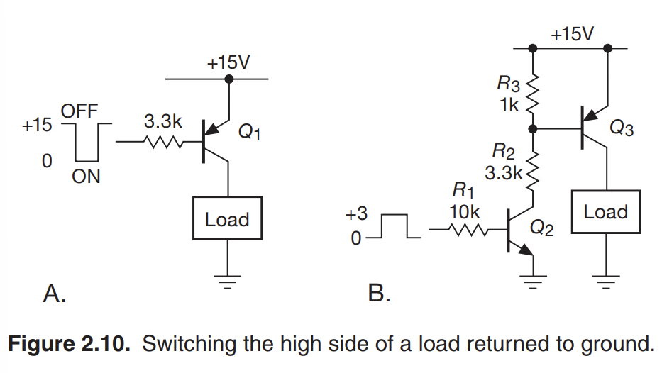
- You could in theory use a pnp junction and have the transistor be off at 15 V
- Ideally, you would want to use a smaller control voltage (like 3.3 V common in digital logic)
- For section B, when NPN receives logic low (0V), Q2 is cut off
- When Q2 is cut off, R3 holds Q3’s base high (ie. off)
- When Q2 is saturated, R2 sinks base current from Q3 to bring it into saturation
Pulse Generator
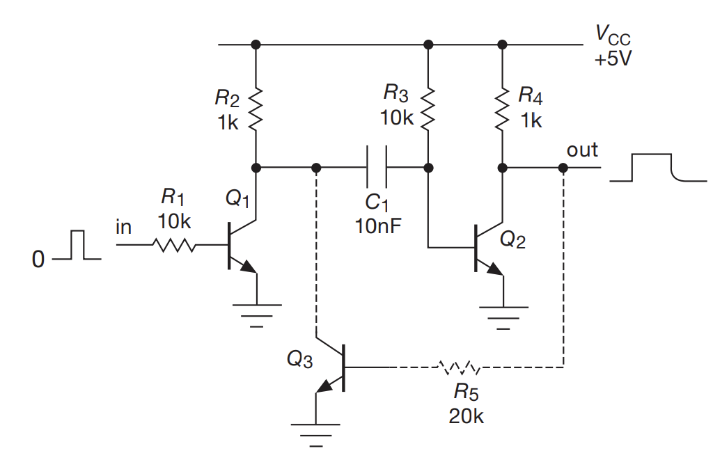
- Above demonstrates a pulse generator, whose width is proportional to the RC time constant at the base
- Normally, C1 is charged due to the difference between R2 and R3, which leaves Q2 saturated, sinking current away from output
- When Q1 gets saturated, C1 discharges, Shutting off Q2, causing the output to rise
- Eventually, C1 is empty, and recharges, resetting the system
Schmitt Trigger
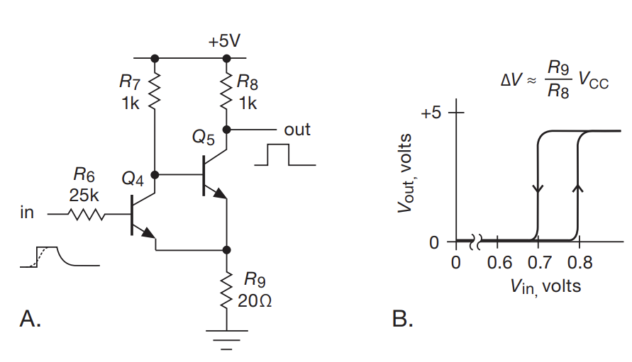
- Q4 starts dropping from high to low. This turns on Q5, which raises the voltage of the emitter of Q4, which causes Q4 to quickly shut off due to not meeting the voltage drop of the transistor
- An analogue thought process turns slow rising edges into fast ones
- You get fun hysteresis effects!
Impedences of Sources and Loads
- Having too high of an output impedance in comparison to the input causes a drop in signal quality due to no longer being in the linear operating region of the transistor
- Rule of thumb is to have a 10x factor
- Like all rules of thumb, there are exceptions:
- If the load is always connected, and there is a known and constant $Z_{in}$, it doesn’t matter if the circuit “loads” the source
- If $Z_{in}$ is variable, then having a small impedence ensures linearity
- If at radiofrequencies, you should try and match impedences to prevent reflections back on the input side
- If the signal being coupled is a current input, then you should strive to have $Z_{in} « Z_{out}$
- If the load is always connected, and there is a known and constant $Z_{in}$, it doesn’t matter if the circuit “loads” the source
Emitter Follower
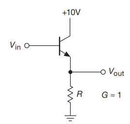
- the impedence at the base is given by $r_{in} = (\beta+1) R$
- Since $\beta$ is like, 100 typically, the input impedence is much higher than the load resistor
- Extending to the complex impedences, we find that
- $Z_{in} = (\beta+1)Z_{load}$
- $Z_{out} = \frac{Z_{source}}{\beta+1}$
- Technically, you need to include the parallel resistance R, but $Z_{out}$ normally dominates this
- Current flows in 1 direction only
- The base emitter reverse breadown voltage is small (~6 V), so put a protective diode from emitter to base if the input will swing that much
- The gain is slightly less than unity
Emitter Follower Biasing
- If you are taking as input an AC signal, there is a good chance that the signal can swing to negative, turning off the transistor prematurely and causinig clipping
- To mitigate this, you need to change the quiescence point (the Q point), which is the DC response of the circuit. This can be done with a voltage divider
- We want to keep the input impedance smaller than the output impedance, which necessitates that $R_{1}|| R_{2} « \beta R_{E}$
Case Study
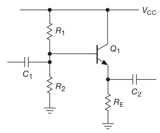
- The above demonstrates an AC-coupled emitter follower. Assume the following:
- that we are taking an audio signal (20Hz to 20 kHz) as input
- $V_{cc}$ is +15V
- the quiescent current is 1mA
- Choosing $V_{E}$: The largest possible symmetrical swing without clipping is have of $V_{cc}$
- Choosing $R_{e}: for a quiescent current of 1mA, we need $R_{E} = 7.5k$
- Setting the bias: we need $V_{B} = V_{E}+0.6V$. This sets the ratio between $R_{1}$ and $R_{2}$ to be 1:1.17. The loading criterion states that the parallel resistance between $R_{1}$ and $R_{2}$ should be less that $\beta R_{E}$. Use standard values of $R_{1}=130k$ and $R_{2} = 150k$
- Choosing C1: C1 will form a high pass filter with the impedance it sees as a load. This consists of
- The voltage divider (which is around 70 from step 3)
- the impedance at the base (which is 750k = $\beta R_{e}$ if you assume that the load is large compared to the emitter resistor)
- The above yields an impedance of roughly 63k, so the capacitor needs to be at least 0.15 uF so that the 3dB point is below 20 Hz
- Choosing C2: C2 forms a high pass with the load impedence. If we assume that the load won’t be smaller than $R_{e}$, then we need C2 to be at least 1.0 uF to set the 3dB point
- Since we have two cascading highpass filters, we want to bump up the capacitor values a bit to prevent excessive attenuation. Hence, C1 = 0.47 uF and C2 = 3.3 uF are sufficient
Canceling Offset
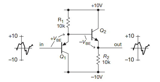
You can (roughly) mitigate the voltage drop of the emitter follower by cascading an pnp transistor with an npn transistor. This mitigates the voltage drop, so you get the reduced impedance benefits without the reduced gain
Transistor Current Sources
- You can have a large R in series with a load resistor. as long as the load is much smaller than R, then you have a current source which is roughly $I \approx \frac{V}{R}$
- This is a crappy current source, since you can’t program it, and you have mad power dissipation
- You can have a transistor act as a constant current source that is (mostly) independent from the supply voltage
- $I_{C} \approx \frac{V_{b} -0.6}{R_{E}}$ for large $\beta$
- The transistor can only provide a constant current over a range of output voltage (otherwise, you get infinite power). This is called compliance
- This current source is programmable (ie. you can change the base voltage to set how much current you want to supply)
- Can mitigate offset using same pnp cascading trick as before
Common-emitter Amplifier
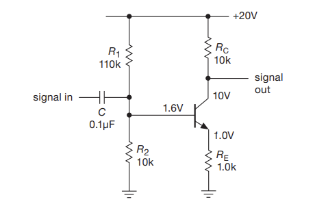
- Collector voltage is given by $V_{C} = V_{CC}-I_{C}R_{C}$
- The blocking capacitor forms a high pass filter with R1 parallel with R2
- Quiescent collector current is about 1.0 mA b/c of base bias and 1k emitter resistor
- $v_{e}= v_{b}$ because of emitter-follower configuration
- The current in the collector is (roughly) the same as that in the emitter. Hence:
- $v_{c} = -i_{c}R_{c} = -v_{b} \frac{R_{c}}{R_{E}}$
- So you phase shift by 180 and increase signal by 10.
- NOTE: You cannot get infinite gain out of this, since the simple beta model isn’t sufficent.
Unity Gain Phase Splitter
- If you set the gain to -1, then you can generate an in phase signal at the emmitter and an out of phase signal at the collector
Phase Shifter
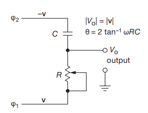
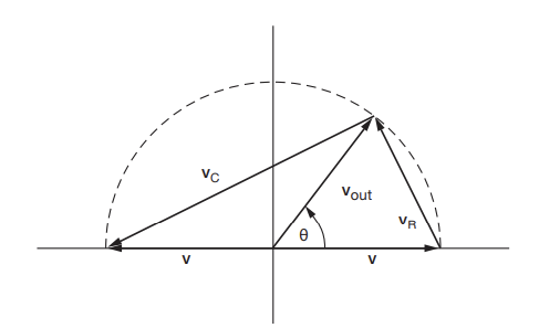
- You can pass the phase splitter signals into a constant amplitude phase shifter
- Since the R and C voltages must be orthogonal to each other, you can use some geometry to see that the amplitude is constant and $\theta$ is governed by the input signal frequency plus R and C
Transconductance
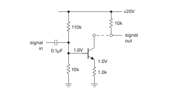
- You can imagine breaking up the emitter amplifier into two parts
- The first part is a voltage controlled current source, with a quiescent current of 1.0 mA and gain of -1mA/V (this has units of conductance (ie. 1/resistance))
- Such an amplifier is called a transconductance amp. The ratio of changes of $\frac{\Delta I_{out}}{\Delta V_{in}} = g$ is called the transconductance
- The second part is a transresistance converter, where the gain is the resistance
- Hence you can get the overall gain by multiplying the two gains
- The first part is a voltage controlled current source, with a quiescent current of 1.0 mA and gain of -1mA/V (this has units of conductance (ie. 1/resistance))
- The above let’s you futz with each part separately
- You need to think of a transistor as a transcoductance device: namely,that the collector current is determined by the base-to-emitter voltage
Ebers-Moll equation
- $I_{C} = I_{S}(T) (e^{\frac{V_{BE}}{V_{T}}}-1)$
- or alternatively $V_{BE} = \frac{kT}{q} log_{e}(\frac{I_{C}}{I_{s}(T)}+1)$
- In the active region, the -1 can be ignored
Rules of thumb
- There are some rules of thumb you can derive the Ebers-Moll equation so that you don’t need to reference it directly
- Base-emitter voltage increases approximately 60 mV per decade of collector current
- The small signal emitter impedance at room temperature $r_{e} = \frac{25}{I_{c}}$ where $I_{c}$ is in milliamps
- The associated transconductance is $\frac{1}{r_{e}} = g_{m}$
- $I_{c}$ increases about 9% per C. It doubles for an 8 C rise
- $\Delta V_{BE} = -\ete \Delta V_{CE}$
- This is the Early effect. $V_{BE}$ linearly varies with $V_{CE}$
- Alternatively, you can express this as $I_{C} = I_{C0}(1+\frac{V_{CE}}{V_{A}})$ where $V_{A}$ is known as the Early voltage
Emitter Follower Redux
- Using Ebers-Molls, we know that there is a nonzero finite impedence on the output
- This explains the the less than unity gain
- The effect of Ebers-Moll is just to add a series emitter resistance $r_{e}$ to the prior results
Bias Stability
- The bias (ie. the DC offset) has a dependency on the temperature and beta. For some applications, we need to DC offset to be resistant to these changes
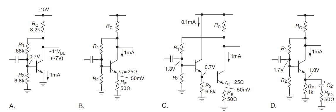
- A: By using the collector voltage instead of VCC, if we get transistor saturation, we have the base and collector voltages move together (in contrast to just the base moving when using VCC)
- This still drifts by ~1V with ambient temps
- B: Reduces gain with $R_{E}$ resistor, but keeps bias more stable
- C: Including a emitter-follower increases input impedance
- D: Everything
Current Mirrors
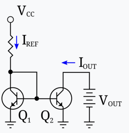
- Current mirrors let you draw out a fixed amount of current from one voltage source based on a current source from another voltage
- The output impedance is not infinite, so the output current varies with the output voltage